
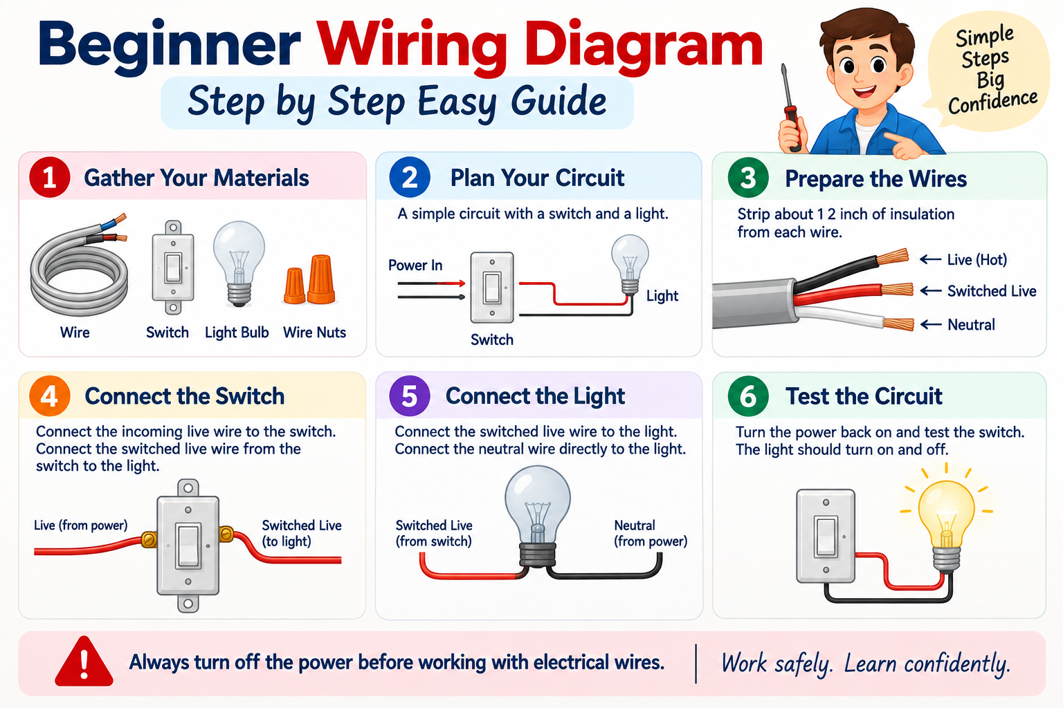
A beginner wiring diagram can look intimidating at first. Lines cross the page. Symbols represent switches lights batteries or other components. Yet the basic idea is much simpler than it appears. A wiring diagram is a visual map that shows how electrical components connect and how current can travel through a circuit.
The biggest mistake beginners make is trying to memorize every symbol before understanding the circuit itself. You don’t need to do that. Start by identifying the power source then follow the path through the components and back to the source. Once you learn that habit a diagram starts to look less like a puzzle and more like a set of directions.
This guide explains how to read simple electrical diagrams step by step. You’ll learn common symbols wire paths circuit basics switches loads power sources and connection points. You’ll also see simple examples and common mistakes. The focus is on understanding the logic behind a circuit so you can read diagrams with confidence. For safety any work involving household mains electricity should be handled according to local electrical codes and by a qualified electrician when required.
Many readers also check Well Deserved Meaning Spelling And Usage.
Quick Definition
A beginner wiring diagram is a simple visual representation of an electrical circuit that shows how components connect. It uses lines and standard symbols to represent wires power sources switches loads and connection points. The diagram helps you understand the circuit before building or troubleshooting it.
Quick Answer
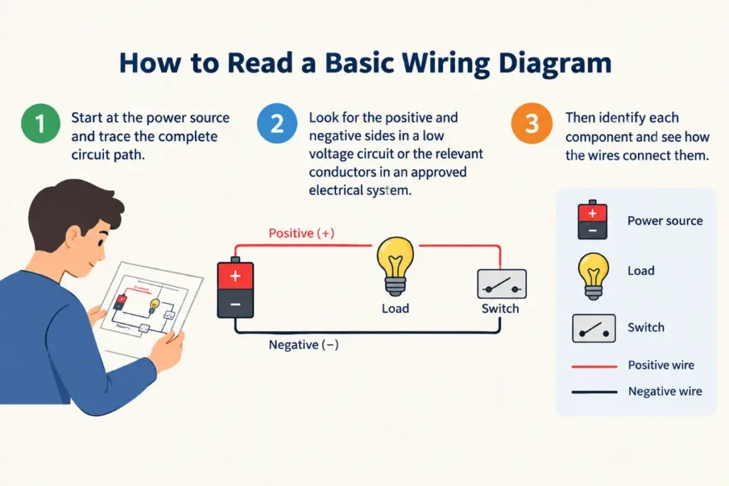
The easiest way to read a basic wiring diagram is to start at the power source and trace the complete circuit path. Look for the positive and negative sides in a low voltage circuit or the relevant conductors in an approved electrical system. Then identify each component and see how the wires connect them.
For learning purposes start with simple low voltage circuits such as a battery connected to a switch and lamp. These circuits help you understand the same basic ideas without exposing you to the hazards associated with household mains electricity.
What A Wiring Diagram Shows
A wiring diagram tells you how electrical components are connected. Think of it as a road map for electricity.
A typical diagram can show a power source a switch a load wires connectors and other components. The exact symbols vary depending on the type of diagram and the drafting standard being used. However the basic purpose stays the same.
The lines normally represent conductors or electrical connections. Symbols represent components. A connection point shows that two or more conductors are electrically joined.
The diagram can also show polarity. This matters in many direct current circuits because reversing positive and negative connections can prevent a circuit from working or damage certain components.
The most useful question to ask is simple.
Where does the electrical path begin and where does it return?
In a basic closed circuit the source provides electrical energy. The conductors provide a path. The load uses electrical energy. The circuit then returns to the source.
Once you understand that relationship you can start reading more complicated diagrams.
Basic Parts Of A Simple Circuit
Power Source
Every working circuit needs a source of electrical energy. In a simple learning circuit that source might be a battery.
A battery has positive and negative terminals. In a direct current circuit you normally identify these clearly before making connections.
Other power sources can include power supplies generators and approved electrical distribution systems. Each type has different safety requirements.
For beginners a small battery is often the easiest place to start because the voltage and available energy can be much lower than household electrical systems.
Conductors
Conductors provide the electrical path between components. In a simple diagram they are usually represented by lines.
A wire shown between a battery and a switch means those components have an electrical connection. Another wire from the switch to the lamp continues the path.
The line itself isn’t the important part. The connection it represents is.
Switch
A switch controls the path of current by opening or closing a circuit.
When a switch is closed the circuit can provide a continuous path. When the switch is open the path is interrupted.
This simple idea appears in countless electrical systems.
A wall switch controlling a light follows the same broad concept as a small switch controlling a low voltage lamp. The physical equipment and safety requirements differ but the circuit logic is familiar.
Load
The load is the component that uses electrical energy.
A lamp is a simple example. Motors heaters buzzers and many electronic devices also act as loads.
In a diagram the load appears as part of the circuit path. Its electrical characteristics determine how much current flows and how the circuit behaves.
Connection Points
Connection points show where conductors join.
This detail matters because crossing lines don’t always mean the wires are electrically connected. A diagram may use a junction symbol or another drafting convention to show an actual connection.
Always inspect junctions carefully rather than assuming that every crossing represents an electrical connection.
How To Read A Wiring Diagram Step By Step
- Find the power source. Identify the battery power supply or other source shown in the diagram.
- Identify the circuit conductors. Follow the lines leaving the source and see where they go.
- Find the control device. Look for a switch relay or another component that controls the circuit.
- Find the load. Identify the lamp motor buzzer resistor or other device that consumes electrical energy.
- Trace the return path. Follow the circuit back toward the power source.
- Check every connection. Make sure you understand which lines are actually joined.
- Look for polarity. In direct current circuits identify positive and negative connections.
- Check component ratings. A diagram can show connections but you still need to verify voltage current power and other ratings before building a circuit.
- Read labels carefully. Component labels often provide information about terminals ratings or functions.
- Trace the circuit again. After you think you understand it follow the complete path one more time from the source and back.
This process is far more useful than trying to memorize an entire diagram at once.
Common Wiring Symbols
Electrical diagrams use symbols because drawing every physical component would make a circuit difficult to read.
Battery
A battery symbol commonly uses alternating long and short parallel lines. The symbol represents a source of direct current electrical energy.
The exact graphical appearance can vary between standards and diagram types.
Switch
A switch is represented by a break in the circuit with a movable contact or another conventional symbol.
An open switch represents an interrupted path. A closed switch represents a completed connection.
Lamp
A lamp is commonly shown using a circle with a symbol inside it. The exact representation depends on the drafting convention.
The key point is that it represents a lighting load.
Resistor
A resistor is represented using a conventional resistor symbol. North American diagrams commonly use a zigzag style while other standards often use a rectangular shape.
Its purpose is to resist current flow and create a specified electrical relationship within the circuit.
Ground
A ground symbol indicates a connection to a reference point or grounding system depending on the circuit.
This symbol requires careful interpretation because circuit reference ground and protective earth are related concepts but aren’t always identical.
Fuse
A fuse is a protective device designed to interrupt a circuit when excessive current causes the fuse element to operate.
The symbol and exact arrangement depend on the diagram standard.
Motor
A motor is often represented by a circle containing a letter or motor designation. It represents an electrical machine that converts electrical energy into mechanical motion.
A Simple Battery Switch And Lamp Circuit
A basic battery switch and lamp circuit is one of the easiest circuits for understanding wiring diagrams.
Imagine a battery connected to a switch. The switch connects to a lamp. The lamp then connects back to the other battery terminal.
The circuit has a simple path.
Battery positive → switch → lamp → battery negative.
When the switch is open the path is interrupted. The lamp remains off.
When the switch is closed the path becomes complete. The lamp can operate if the battery and lamp are appropriately rated.
This example teaches several important ideas at once. You can see the power source the control device the load the conductors and the return path.
It also shows why a complete circuit matters. Connecting one side of a lamp to a battery doesn’t create a working circuit by itself. The electrical path must be completed.
Series And Parallel Connections
Understanding series and parallel circuits is one of the biggest milestones for a beginner.
Series Circuits
In a series circuit components share one continuous path.
Imagine two lamps connected one after another. The current has one primary route through both.
If the circuit is opened at one point the path is interrupted.
Series connections are useful for learning basic circuit behavior but they aren’t appropriate for every practical application.
Parallel Circuits
A parallel circuit provides multiple branches.
Imagine two lamps connected across the same supply. Each lamp has its own branch while both branches connect across the source.
This arrangement is common in many practical electrical systems because one branch can operate independently of another under suitable conditions.
The distinction is simple.
Series means one main path.
Parallel means multiple paths.
Once you can recognize these structures you’ll find many diagrams easier to understand.
Understanding Polarity
Polarity matters most in direct current circuits.
A battery has positive and negative terminals. Many electronic components also have polarity requirements.
For example an LED usually needs to be connected in the correct direction. A polarized capacitor also requires attention to its terminal orientation.
A diagram may use plus and minus symbols or labels to identify polarity.
Never assume that reversing a connection is harmless. The result depends on the component.
One of the best beginner habits is to mark positive and negative clearly before making a low voltage connection.
Understanding Wire Connections
A line on a diagram normally represents an electrical conductor. But the way lines meet matters.
Two lines may cross without being electrically connected. A junction can indicate that they are joined.
Different drawing standards use different conventions. Some diagrams use a dot at a junction while others rely on the way lines are drawn or use terminal labels.
Never guess when a connection is unclear.
Look for the diagram legend labels terminal numbers or the drafting convention used for the drawing.
This becomes especially important as circuits become more complex.
Wire Labels And Terminal Numbers
Many diagrams use labels instead of drawing long wires across an entire page.
For example a terminal might be identified with a number or letter. The same label can appear elsewhere in the diagram to show that the electrical connection continues.
This keeps complicated drawings readable.
Automotive diagrams often use connector numbers terminal numbers wire colors and component identifiers. Industrial diagrams can use terminal blocks and reference designations.
A beginner may initially think these labels make diagrams harder. In practice they make large systems much easier to follow once you know how the references work.
Wiring Diagram Vs Schematic Diagram
People often use wiring diagram and schematic diagram as if they mean exactly the same thing. They’re related but they can serve different purposes.
A wiring diagram generally focuses on physical connections and can show how components are wired together.
A schematic usually focuses more strongly on electrical function and circuit logic. It may not represent the physical location or exact routing of every conductor.
For example a schematic may show a switch controlling a motor without showing the physical route of the wires. A wiring diagram may provide more information about terminals and actual connections.
The distinction isn’t absolute because different industries use these terms differently. Always consider the purpose of the drawing.
Wiring Diagram Vs Layout Diagram
A wiring diagram tells you about electrical connections. A layout drawing focuses more on physical arrangement.
Imagine a control panel containing several switches and indicators.
The wiring diagram explains which terminals connect to which components. The layout drawing can show where those components physically sit on the panel.
These drawings work together but answer different questions.
If you’re trying to understand circuit function start with the schematic or wiring information. If you’re trying to locate a physical component look at the layout.
Why Wire Color Matters
Wire colors can help identify conductors but color conventions vary by application and region.
In low voltage hobby circuits you may choose colors simply to make positive and negative connections easy to recognize. In professional electrical systems color coding follows applicable standards and project requirements.
Never rely on color alone.
A previous installation may contain errors. Wires can also be repurposed or labeled differently depending on the system.
Always verify a conductor using the appropriate documentation and safe testing method.
For household electrical work especially don’t assume a wire is safe simply because of its color.
Basic Electrical Terms Beginners Should Know
Voltage
Voltage describes electrical potential difference. It is measured in volts.
You can think of voltage as the electrical pressure that drives current through a circuit.
That comparison is only an analogy but it can help when you’re first learning.
Current
Current describes the flow of electric charge. It is measured in amperes.
The amount of current depends on the circuit conditions including voltage resistance and the characteristics of connected components.
Resistance
Resistance describes how strongly a component opposes current. It is measured in ohms.
The basic relationship between voltage current and resistance is expressed by Ohm’s law.
V = I × R.
Here V represents voltage. I represents current. R represents resistance.
Power
Electrical power describes the rate at which electrical energy is transferred or used. It is measured in watts.
For a simple direct current circuit you can use:
P = V × I.
These four concepts form the foundation of basic circuit understanding.
You may also want to read Unphased or Unfazed Meaning And Usage Guide 2026.
A Simple Example Using Ohm’s Law
Suppose you have a low voltage circuit with a 12 volt supply and a 6 ohm resistive load.
Using Ohm’s law:
I = V ÷ R.
So:
I = 12 ÷ 6.
The current is 2 amperes under the assumed conditions.
The example is intentionally simple. Real components can behave differently from ideal resistors and many loads don’t maintain constant resistance.
The lesson is more important than the arithmetic. A wiring diagram shows the connections but electrical calculations help you determine what happens in the connected circuit.
That distinction matters.
A diagram can tell you where a component connects. It doesn’t automatically tell you if the component is correctly rated for the application.
How To Follow A Circuit Path
One of the strongest skills you can develop is circuit tracing.
Start at the source.
Follow the conductor to the first component.
Identify what that component does.
Continue to the next connection.
Keep going until you reach the return path.
Then repeat the process in the opposite direction.
If the diagram contains branches trace each branch separately. Ask what happens when a switch opens or closes.
For troubleshooting you can also ask where the circuit stops behaving as expected.
For example if a lamp doesn’t turn on you might inspect the power source the switch the connections and the lamp itself. In a real electrical system safe testing procedures and suitable instruments are essential.
Circuit tracing gives you the mental framework. Testing confirms what is actually happening.

Common Beginner Wiring Mistakes
Assuming Every Crossing Is A Connection
Two lines can cross without being electrically joined.
Always check the drawing convention and junction indicators.
Ignoring Polarity
Reversing positive and negative connections can damage components or prevent operation.
Check polarity before powering a low voltage circuit.
Choosing Wire Based Only On Appearance
A wire that looks thick enough isn’t automatically suitable.
Wire selection depends on factors such as current capacity insulation temperature conditions length installation method and applicable standards.
Forgetting The Return Path
Beginners sometimes focus on the wire going to the load and forget that a complete circuit needs a return path.
Always trace the full loop.
Connecting Power Before Checking The Circuit
Never rush to energize an unfamiliar circuit.
Review the diagram first. Confirm the component ratings and inspect connections before applying power.
This habit can prevent avoidable damage.
Safety Rules For Beginners
Electrical safety deserves more attention than any diagram symbol.
A small battery powered circuit and a household electrical circuit are not equivalent risks.
Low voltage does not automatically mean zero risk either. Batteries can deliver substantial current and can cause burns short circuit damage or other hazards under certain conditions.
For basic learning projects use appropriate low voltage equipment and follow the component manufacturer’s instructions.
For household mains systems use the applicable electrical code and local requirements. If you don’t have the training and authorization required for the work contact a qualified electrician.
Never experiment with exposed mains wiring simply to learn how a diagram works.
A wiring diagram is educational. It doesn’t replace proper training safe isolation procedures electrical testing knowledge or local code requirements.
Tools Beginners May Encounter
You don’t need a large toolbox to learn circuit theory.
A basic low voltage learning setup might include a suitable power source switches loads connecting wires and an appropriate meter.
A digital multimeter can measure electrical quantities such as voltage resistance and current depending on the instrument and how it is used.
However measuring current requires special care because a meter can create an unintended low resistance path if connected incorrectly.
For beginners the safest approach is to learn what each meter function does before connecting the instrument to a powered circuit.
Never assume that a meter setting is harmless.
How To Check A Diagram Before Building
Before connecting anything take a few minutes to review the drawing.
- Identify the source and confirm its voltage.
- Identify every component.
- Check component ratings.
- Trace the complete circuit path.
- Look for branches.
- Confirm polarity where applicable.
- Check terminal labels.
- Look for fuses or other protective devices where the design requires them.
- Confirm that the wire and connectors are suitable.
- Review the circuit one final time before applying power.
This short checklist can catch many mistakes before they become hardware problems.
How To Draw Your Own Simple Circuit
You can begin with something as simple as a battery switch and lamp.
First place the battery on the page.
Then place the switch in the circuit path.
Add the lamp after the switch.
Finally draw the return connection to the battery.
Label the positive and negative sides.
Then show the switch in its intended state.
Keep the drawing clean. Avoid unnecessary line crossings. Use clear labels and consistent symbols.
The goal isn’t to make the diagram artistic. The goal is to make the electrical relationship obvious to another person.
A good diagram should answer the question where does this connection go without making the reader hunt around the page.
How To Make A Diagram Easier To Understand
Good diagrams have a kind of visual grammar.
Use consistent symbols.
Keep related components close together when possible.
Avoid unnecessary crossings.
Label important terminals.
Show polarity when it matters.
Use a legend when the symbols aren’t obvious.
If a circuit has several sections separate them logically.
For a complicated system use reference labels so a reader can move from one section to another.
Remember that a diagram is communication. You’re not drawing only for yourself. Another person may need to troubleshoot the circuit months later.
Clarity saves time.
Reading Automotive Wiring Diagrams
Automotive diagrams can look much more complicated than simple battery circuits.
They may contain batteries fuses relays switches motors sensors connectors control modules and multiple wire paths.
A beginner should start with one circuit rather than trying to understand the entire vehicle diagram at once.
Find the power source.
Locate the fuse or protection device.
Trace the wire to the switch relay or control module.
Find the load.
Then trace the return path.
Connector numbers and terminal labels become especially important in automotive work.
Wire colors can also provide clues but should never replace the actual diagram and proper testing.
Automotive electrical systems can contain high current circuits. Follow the vehicle manufacturer’s service information and appropriate safety procedures before testing or modifying anything.
Reading Household Electrical Diagrams
Household electrical diagrams require much more caution.
A typical residential system involves hazardous voltage and can cause severe injury or death.
The same basic concepts still apply. You can identify a source conductors switches loads protective devices and return paths.
But understanding the diagram doesn’t automatically qualify someone to perform the installation.
Residential wiring must comply with the electrical requirements that apply to the location. Requirements can cover conductor sizing protection grounding boxes connections switches outlets and many other details.
If you’re studying a household diagram for educational purposes focus on understanding the circuit logic. For actual installation or modification use the applicable code and qualified professional guidance.
Why A Fuse Or Breaker Matters
Protective devices are designed to help prevent dangerous overcurrent conditions.
A fuse contains an element designed to interrupt the circuit under specified conditions. A circuit breaker can also interrupt current when its operating conditions are met.
These devices must be selected and installed correctly.
A common beginner mistake is thinking that a larger fuse is better because it is less likely to blow.
That can be extremely dangerous.
The protective device must be appropriate for the circuit conductors and equipment according to the design and applicable requirements.
Never replace a protective device with a higher rated one simply to stop nuisance operation.
If a fuse repeatedly opens or a breaker repeatedly trips the underlying problem needs attention.
Understanding Open And Closed Circuits
An open circuit has an interruption in the intended electrical path.
A closed circuit has a complete path that allows current to flow under the circuit conditions.
A switch gives you a simple example.
Switch open means the intended path is interrupted.
Switch closed means the path is completed.
This terminology appears throughout electrical work.
When troubleshooting a circuit the question is often where did the expected path become open or where did an unintended path appear?
That way of thinking is useful because it turns a complicated problem into a series of smaller questions.
Troubleshooting From A Diagram
A diagram can become a powerful troubleshooting tool.
Suppose a low voltage lamp doesn’t work.
Start at the source. Is the supply present and appropriate?
Then inspect the path to the switch.
Check the switch.
Continue toward the lamp.
Check the lamp connections.
Finally check the return path.
A multimeter can help verify electrical conditions when used correctly.
The key is to test logically rather than randomly replacing parts.
A good troubleshooter uses the diagram as a map and measurements as evidence.
That approach is much more reliable than guessing.
Related Electrical Diagram Types
A beginner will eventually encounter several types of electrical drawings.
Schematic
A schematic emphasizes electrical function and logical relationships.
Wiring Diagram
A wiring drawing focuses more directly on connections between components.
Block Diagram
A block diagram simplifies a system into major functional sections.
Ladder Diagram
Ladder diagrams are widely used in industrial control systems and represent control logic using a ladder like structure.
Single Line Diagram
A single line diagram simplifies electrical distribution systems by representing circuits with a single line and standardized symbols.
Layout Drawing
A layout drawing emphasizes physical placement.
Learning these categories helps you understand why two drawings of the same system can look completely different while still describing the same equipment.
Expert Editor Insight
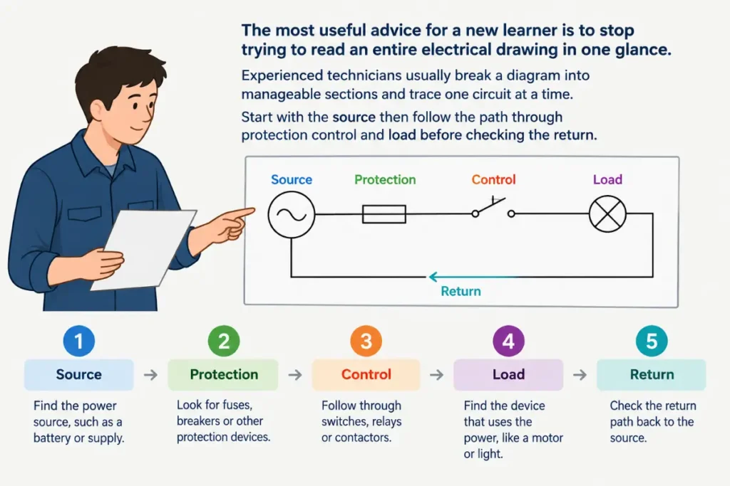
The most useful advice for a new learner is to stop trying to read an entire electrical drawing in one glance. Experienced technicians usually break a diagram into manageable sections and trace one circuit at a time. Start with the source then follow the path through protection control and load before checking the return. Also pay attention to terminal labels because they often provide more reliable information than color alone. A clean diagram should explain the intended electrical relationship without forcing the reader to guess.
Learn the difference in Busing or Bussing Grammar Rules and Usage Guide 2026.
Conclusion
A beginner wiring diagram becomes much easier to understand once you stop seeing it as a collection of strange symbols and start seeing it as a map of an electrical path. Begin at the power source then follow the conductors through the controls and loads until you reach the return path. That simple habit gives you a reliable foundation for reading more complex drawings.
The most useful concepts to master first are voltage current resistance power polarity open circuits closed circuits and the difference between series and parallel connections. Learn common symbols gradually and pay close attention to junctions terminal labels and circuit references.
For practice start with simple low voltage circuits before studying more advanced systems. Keep one safety rule firmly in mind: understanding a diagram doesn’t make hazardous electrical work safe. Use proper training and applicable electrical requirements whenever real installation work is involved.
FAQs
What is the easiest way to read a wiring diagram?
Start with the power source and trace the electrical path one component at a time. Identify the switch or control device then locate the load and follow the return path. Pay attention to junctions labels polarity and component symbols. Don’t try to understand a large diagram all at once. Break it into small circuits and build your understanding from there.
What should a beginner learn first about electrical wiring?
Start with basic circuit concepts rather than physical installation. Learn voltage current resistance power open circuits closed circuits series connections and parallel connections. Then learn common symbols and how to trace a circuit from its source through a load and back. Once those ideas make sense you’ll find more complicated electrical drawings much easier to follow.
What do the lines mean on an electrical diagram?
Lines generally represent electrical conductors or connections between components. They show the intended path between parts of the circuit. However a line crossing another line doesn’t always mean the two conductors are connected. The diagram’s drafting convention determines how junctions are shown. Look for junction symbols terminal labels or other connection indicators before assuming two conductors are electrically joined.
How do you know which wire goes where?
Use the diagram labels terminal numbers connector information and circuit references to identify the intended connection. Never rely only on wire color because colors can vary by application and an existing installation can contain errors. For actual electrical work use appropriate documentation and safe testing methods. Household mains wiring should be handled according to local requirements by properly qualified people.
What is the difference between a schematic and a wiring diagram?
A schematic generally focuses on how a circuit functions and how its electrical components relate to one another. A wiring diagram usually provides more detail about actual connections between components. The terminology can vary across industries so the distinction isn’t absolute. When reading a drawing look at its purpose. One drawing may explain circuit logic while another helps identify physical connections and terminals.
Can you learn electrical wiring without experience?
You can learn the basic theory without previous experience. Start with low voltage educational circuits and learn how power sources switches loads conductors and protection work together. Physical electrical installation is a different matter. Working on household mains systems involves serious hazards and code requirements. Study the theory first and get appropriate hands on training before attempting practical work that presents an electrical shock or fire risk.
What is the most common beginner mistake when reading a circuit?
One common mistake is looking at individual wires without understanding the complete circuit path. A beginner may see a wire going to a lamp but forget that the circuit also needs a return path. Another common problem is assuming that every crossing is a connection. Trace the entire circuit from the source through each component and back before deciding how it works.
Is a wiring diagram enough to safely install electrical wiring?
No. A diagram shows intended connections but it doesn’t replace electrical knowledge training safety procedures equipment ratings or applicable codes. Safe installation also depends on conductor sizing protective devices grounding methods enclosures connections environmental conditions and many other factors. For hazardous electrical systems especially household mains work use the applicable local requirements and qualified professional assistance instead of relying on a diagram alone.